
Hardware Reference
Specifications
Optical flow sensor
PixArt PAA3905, 42° field of view
Flow working range
80 mm to infinity
Flow features
Detects challenging conditions such as checkerboards, stripes, glossy surfaces and yawing, and switches operation mode automatically
IR LED
40 mW, on the board for improved low light operation
Distance sensor
Broadcom AFBR-S50LX85D time-of-flight
Distance range
Typically up to 50 m; see ARK DIST Range
Laser opening angle
2° × 2°
IMU
InvenSense IIM-42653, 6-axis
MCU
STM32F412VG
CAN
2× Pixhawk-standard 4-pin JST-GH. ROS 2 through ros2_dronecan
Debug
Pixhawk-standard 6-pin JST-SH
Power
5 V, 86 mA average, 90 mA max
Dimensions
3 × 3 × 1.4 cm
Weight
5 g
Pinout
CAN (×2) — 4-pin JST-GH
1
5V
5.0 V
2
CAN_P
5.0 V
3
CAN_N
5.0 V
4
GND
GND
Debug — 6-pin JST-SH
1
3.3V
3.3 V
2
USART2_TX
3.3 V
3
USART2_RX
3.3 V
4
FMU_SWDIO
3.3 V
5
FMU_SWCLK
3.3 V
6
GND
GND
LEDs
Green, fast blink (10 Hz)
Node firmware running. It does not change with CAN traffic.
Green, slow blink (1 Hz)
Bootloader listening for CAN traffic
Blue, blinking (2 Hz)
Bootloader waiting for a node ID from the flight controller
Blue and green, blinking (3 Hz)
Bootloader waiting up to 3 s for the flight controller to start a firmware update
Red, green and blue together (3 Hz)
Firmware update in progress
Red, blinking
Firmware update error. 1 Hz: the flight controller returned a file error. 2 Hz: the flight controller stopped responding. 4 Hz: the image failed its CRC check. A failed update restarts the node after 20 s.
Without valid firmware the node stays in the bootloader until the flight controller flashes it.
Wiring
The ARK Flow MR is connected to the CAN bus using a Pixhawk standard 4 pin JST GH cable. For more information, refer to the CAN Wiring instructions.
Multiple sensors can be connected by plugging additional sensors into the ARK Flow MR's second CAN connector.
Mounting
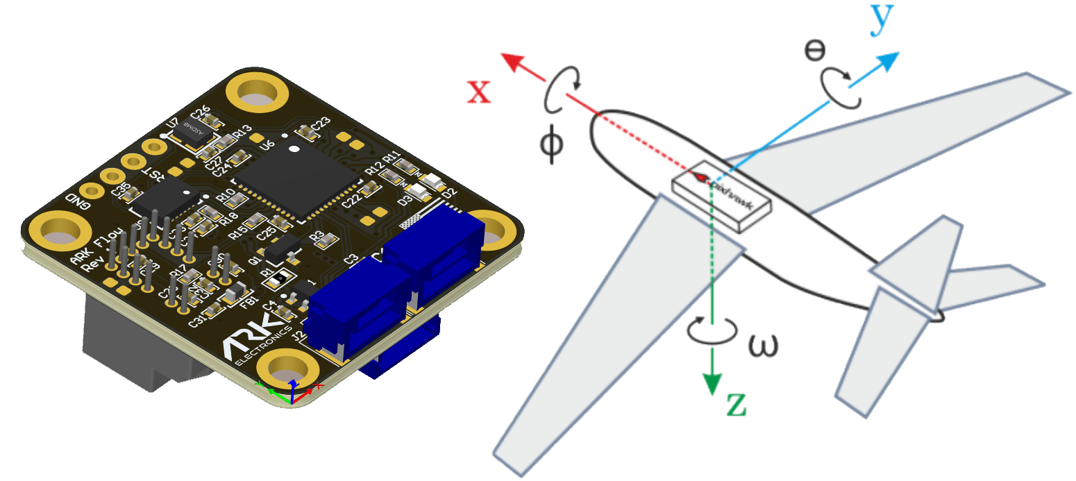
The recommended mounting orientation is with the connectors on the board pointing towards back of vehicle, as shown in the following picture.
3D Model and Case
Board, rev 1.0
Case top, rev 1
Case bottom, rev 1
All files: ARK_Flow_MR in ark-hardware
Last updated